PDF Design of Voltage Controlled Oscillator in 180 nm CMOS Technology Circuit Diagram
PDF Design of Voltage Controlled Oscillator in 180 nm CMOS Technology Circuit Diagram -Ring Oscillator -Crystal resonator •Design of oscillators -Frequency control, stability -Amplitude limits -Buffered output -isolation -Bias circuits -Voltage control -Phase noise. 2 Oscillator Requirements •Power source •Frequency-determining components •Active device to provide gain •Positive feedback

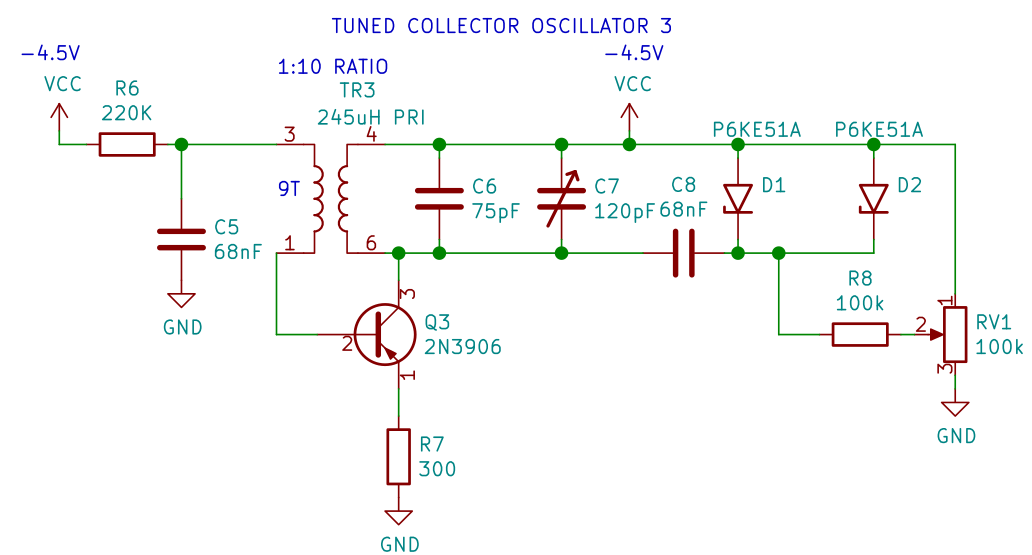
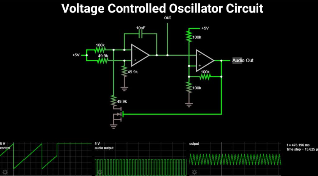
Theory: We are currently modulating voltage with a potentiometer. If the frequency is altered based on this change in DC voltage, a change in DC voltage from a different source should also modulate the frequency. Practice: You want the voltage from your sensing circuit to match the voltage range you identified by sweeping voltages above. If Oscillator Design. According to the book Oscillator Design and Computer Simulation, a bipolar junction transistor (BJT) can be a good choice for an oscillator in the VHF or UHF range. The book describes an example 300 MHz oscillator using a series inductor and capacitor (LC) circuit (L1 and C6 in the circuit diagram below, 100nH and 3pF The chip we will use is a 4046 chip. This is phase-locked loop IC. We will use the VCO portion of it to create our voltage-controlled oscillator circuit. The voltage-controlled oscillator, as its output, produces digital signals that can function as clock signals.
![[PDF] Foundations of Oscillator Circuit Design Circuit Diagram](https://d3i71xaburhd42.cloudfront.net/e55df1d280e8bec52609cc1c74eca03713ada90e/53-Figure1.29-1.png)
PDF Oscillator Design Circuit Diagram
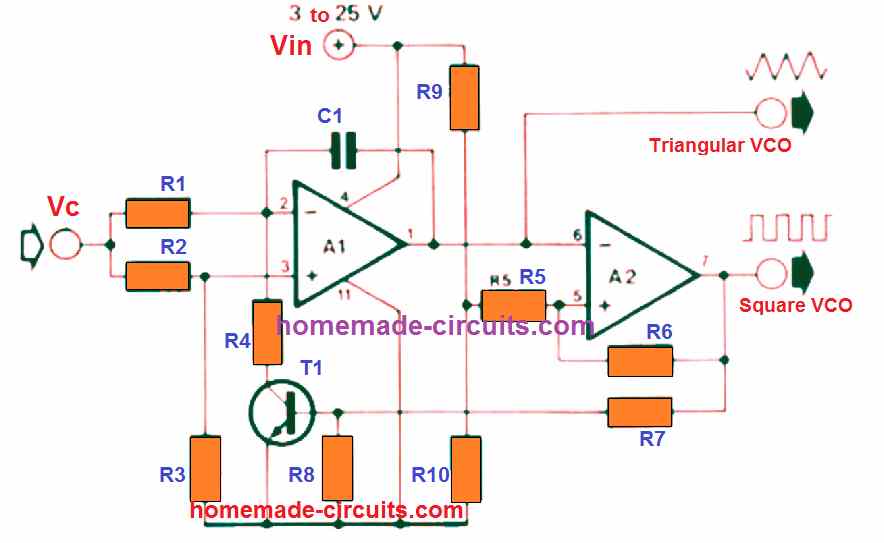
The value of output frequency is adjustable using the Control voltage (on pin 5) with a ratio of 10:1, which helps us in providing a wide range of control. Applications of Voltage Controlled Oscillators (VCO) Frequency Shift Keying; Frequency identifiers; Keypad Tone recognizers; Clock/Signal/Function Generators; Used to build Phase Locked The Analog Group, of the UW ASIC Group, has decided to concurrently design two different VCO (Voltage Controlled Oscillator) topologies. This introduction provides some of the reasoning for why the Analog Group has chosen to design VCOs that have the ring oscillator and the LC tank topology. There are two types of VCOs that one may choose to
The circuit is constructed around a CD4046B phase-locked loop (PLL) integrated circuit with a built-in voltage-controlled oscillator (VCO). The voltage level at pin 9, value of capacitor C1 between pins 6 and 7, potentiometer R1 setting at pin 11, and potentiometer R2 at pin 12 control the frequency of the VCO.
PDF LC Tank Voltage Controlled Oscillator Tutorial Circuit Diagram
Sensitivity to RF choke characteristics is common to all oscillator circuits that use chokes for shunt-feeding the DC operating voltage to the oscillator. References: 1. Alpha Industries - VCO Application notes. 2. Minicircuits - VCO Application notes. 3. Oscillator Basics and Low-Noise Techniques for Microwave Oscillators and VCOs - U.Rohde. 4.